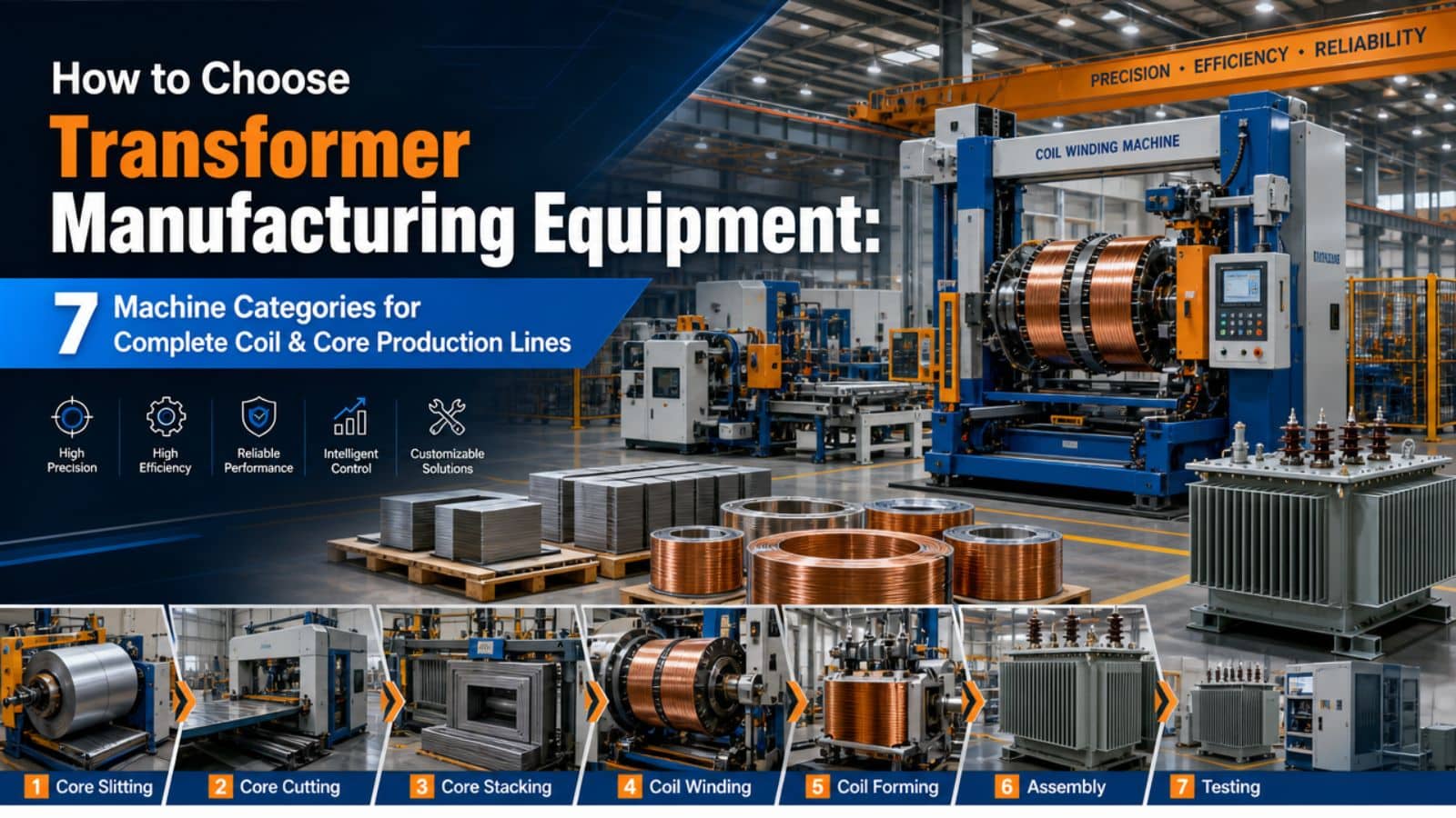
Transformer coil winding is one of the most critical stages in transformer manufacturing. The geometry, tension consistency, and insulation integrity of each winding layer directly determine the unit’s electrical performance, thermal behavior, and long-term reliability. Choosing the right transformer winding machine for your production mix—whether you build distribution transformers, power transformers, or specialty reactors—can mean the difference between a stable 30-year asset and a premature field failure.
In this guide, we break down the main categories of winding equipment, explain what each machine type is engineered for, and help you match machine capability to coil specification.
Why Winding Technology Matters More Than Ever
Modern transformer designs are pushing higher voltage classes, lower losses, and more compact footprints. That translates into:
- Thinner conductor profiles and tighter dimensional tolerances
- Complex layer insulation schemes (paper, epoxy, or oil-impregnated)
- Mixed conductor types: round wire, flat copper, continuous transposed cable (CTC), and aluminum foil
A manual or outdated winding setup cannot hold the tension repeatability or layer registration required for these designs. Automated winding systems with programmable tension, automatic layering, and real-time correction have become the baseline for Tier-1 and Tier-2 transformer factories.
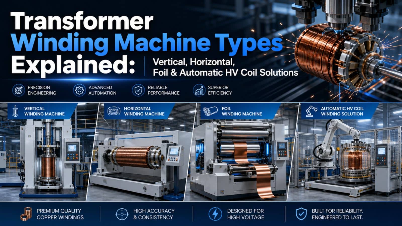
Vertical Winding Machine
Best for: Large power transformer coils, disc-type windings, and high-voltage layers where gravity-assisted conductor laying improves stability.
In a Vertical Winding Machine, the coil mandrel stands upright and rotates around a vertical axis. The conductor is fed from above or below, allowing the winding head to travel vertically as each turn builds up.
Key advantages:
- Gravity helps seat each turn firmly against the previous layer, reducing inter-layer voids
- Easier access for inter-layer insulation insertion (pressboard, crepe paper, or diamond-dotted paper)
- Ideal for tall, narrow coil geometries common in shell-form and core-form power transformers
Typical specifications to evaluate: mandrel diameter range, max coil weight capacity, vertical stroke length, and whether the machine includes an automatic wire guide traverse.
Horizontal Winding Machine
Best for: Distribution transformer coils, helical windings, and low-voltage layers where wide coil diameters and shorter axial lengths are standard.
The Horizontal Winding Machine rotates the mandrel around a horizontal axis. This orientation makes it easier to handle wide, pancake-style coils and simplifies loading/unloading with overhead cranes or coil carts.
Key advantages:
- Excellent for layer-type LV windings with large conductor cross-sections
- Simpler integration with foil winding attachments
- Often preferred for workshop layouts with limited vertical clearance
When evaluating horizontal winders, look at mandrel expansion range, tailstock clamping force, and the availability of counter-roller systems to prevent conductor twist on wide coils.
Foil Winding Machines: Single Layer & Double Layer
Best for: Low-voltage foil windings in dry-type and oil-immersed distribution transformers.
Foil winding replaces traditional round or flat wire with thin aluminum or copper foil, interleaved with insulating foil (typically polyester or Nomex). This construction improves eddy-current loss distribution and enhances short-circuit withstand.
- Single Layer Foil Winding Machine: Wound with one conductor foil strip. Common in smaller kVA units.
- Double Layer Foil Winding Machine: Wound with two parallel foil strips, often used when current capacity exceeds the practical width of a single foil roll.
Critical machine features include automatic edge-alignment sensors, foil tension control with dancer arms, and integrated insulation foil payoff stands. The Payoff Stand that feeds foil and insulation material into the winder must maintain synchronized tension to avoid wrinkles or misalignment that could create partial discharge paths.
Automatic High Voltage Winding Machines
As voltage class increases, so does the complexity of winding inter-layer insulation, shielding, and tap leads. Two specialized configurations dominate this segment:
Automatic High Voltage Winding Machine for Large Transformer Coils
- Designed for 66 kV to 800 kV+ class coils
- Programmable traverse with micron-level accuracy
- Automatic paper or pressboard insertion between layers
- Integrated lead forming and taping stations
- Often paired with an Expandable Winding Mandrel that collapses for easy coil extraction without deforming the finished winding
Automatic High Voltage Winding Machine for Distribution Transformer Coils
- Optimized for 11 kV to 35 kV classes
- Faster cycle times and smaller mandrel formats
- May include automatic conductor splicing and end-insulation taping
- Suitable for high-mix, medium-volume production environments
Both systems typically incorporate Wire Taping Machine integration or inline taping heads that apply insulation tape to conductor junctions and lead exits during the winding process.
Core Coil Winding Machine 3D
Best for: Reactor coils, interleaved windings, and non-standard coil geometries.
Standard winding machines move in two axes (mandrel rotation + traverse). A Core Coil Winding Machine 3D adds a third programmable axis—often a tilting or offset winding head—that can create non-cylindrical coil shapes, tapered sections, or precisely controlled crossover patterns.
This capability is essential for:
- Shunt reactor coils with graded insulation
- Tapped winding sections with axial displacement
- Specialty instrument transformer coils
Expandable Winding Mandrel & Payoff Stand: The Unsung Heroes
No winding line is complete without proper material handling.
- Expandable Winding Mandrel: Expands mechanically to grip the inner diameter of the coil form, then contracts after winding so the finished coil can be lifted off without distortion. Look for hydraulic or mechanical expansion systems with uniform radial pressure distribution.
- Payoff Stand: Holds conductor reels, foil rolls, or insulation spools and maintains constant back tension. Poor payoff design causes tension spikes that translate into loose turns, conductor stretch, or insulation damage.
How to Choose the Right Winding Configuration
| Your Product Mix | Recommended Winding Setup |
|---|---|
| Distribution transformers (≤ 35 kV) | Horizontal + Single/Double Foil Winding |
| Medium power transformers (66–220 kV) | Vertical Winding + Automatic HV Winder |
| Large power / UHV transformers (≥ 330 kV) | Vertical + Automatic HV for Large Coils + 3D capability |
| High-volume, standardized designs | Fully automatic lines with automatic layering |
| Low-volume, high-customization | Semi-automatic with quick-change mandrels |
Conclusion
Transformer winding is not a one-machine-fits-all process. The right combination of Vertical Winding Machine, Horizontal Winding Machine, Foil Winding Machine, and Automatic High Voltage Winding Machine—supported by precision Expandable Winding Mandrels and Payoff Stands—determines your coil quality, production throughput, and scrap rate.
If you are planning a new transformer factory or upgrading an existing winding shop, mapping your coil portfolio to machine capability is the first step. A well-specified winding line pays for itself through reduced rework, faster throughput, and coils that meet IEC, IEEE, or customer-specific test regimes on the first attempt.